Printed circuit boards are simple devices. They are layers of glass fiber onto which a circuit is projected in a number of steps. Nowadays the whole process is heavily automated, and so it is swift and efficient. During manufacturing, humans oversee the machinery to ensure that the outcome is perfect and the best it can be.
In this article, we will go through the main steps of PCB production. There are some explanations and visual representations of the different processes. This way the steps can be easily followed and understood. Every order on PCBnow goes through a similar process, ensuring the very best quality of PCBs, produced fast and effiecently.
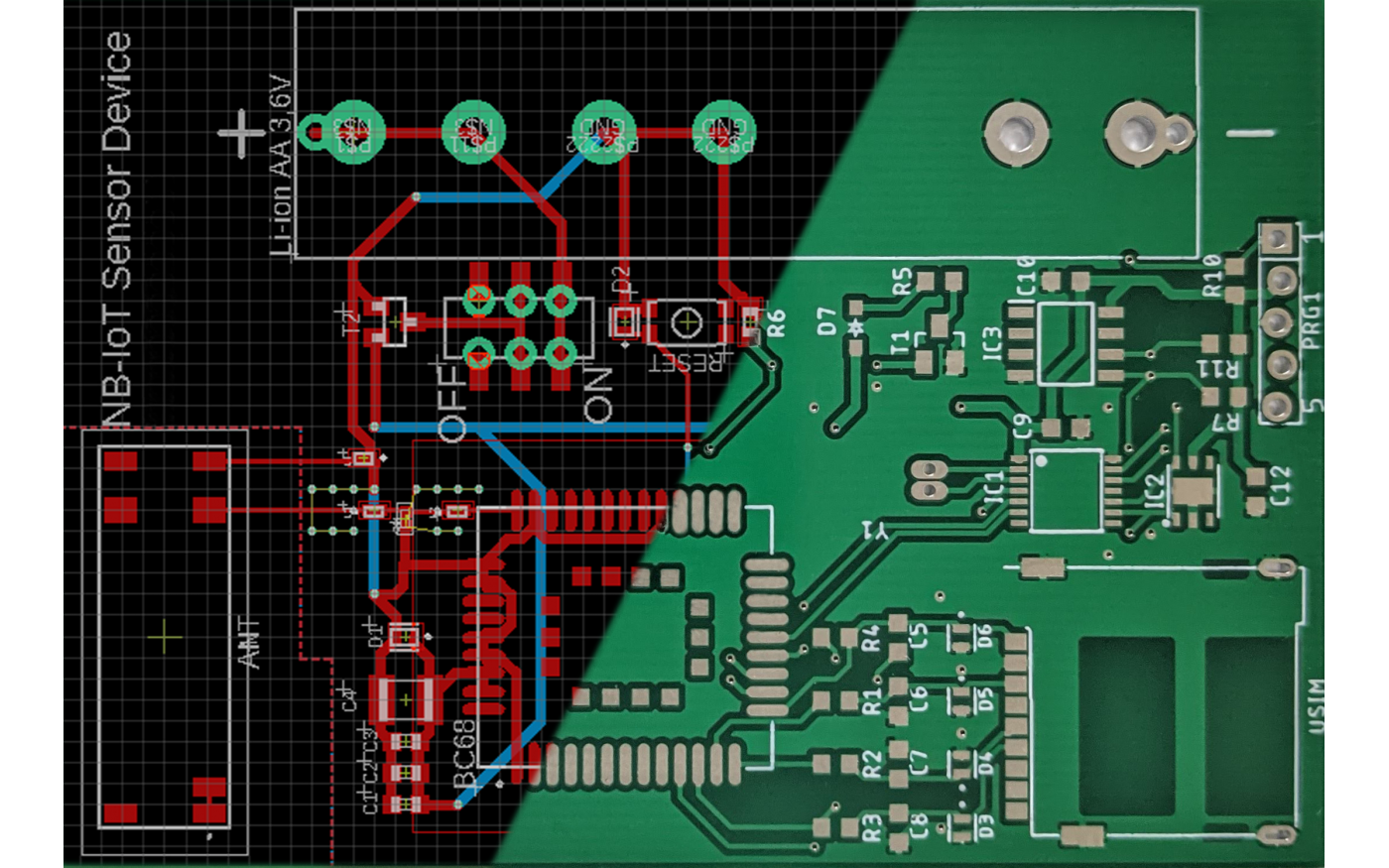
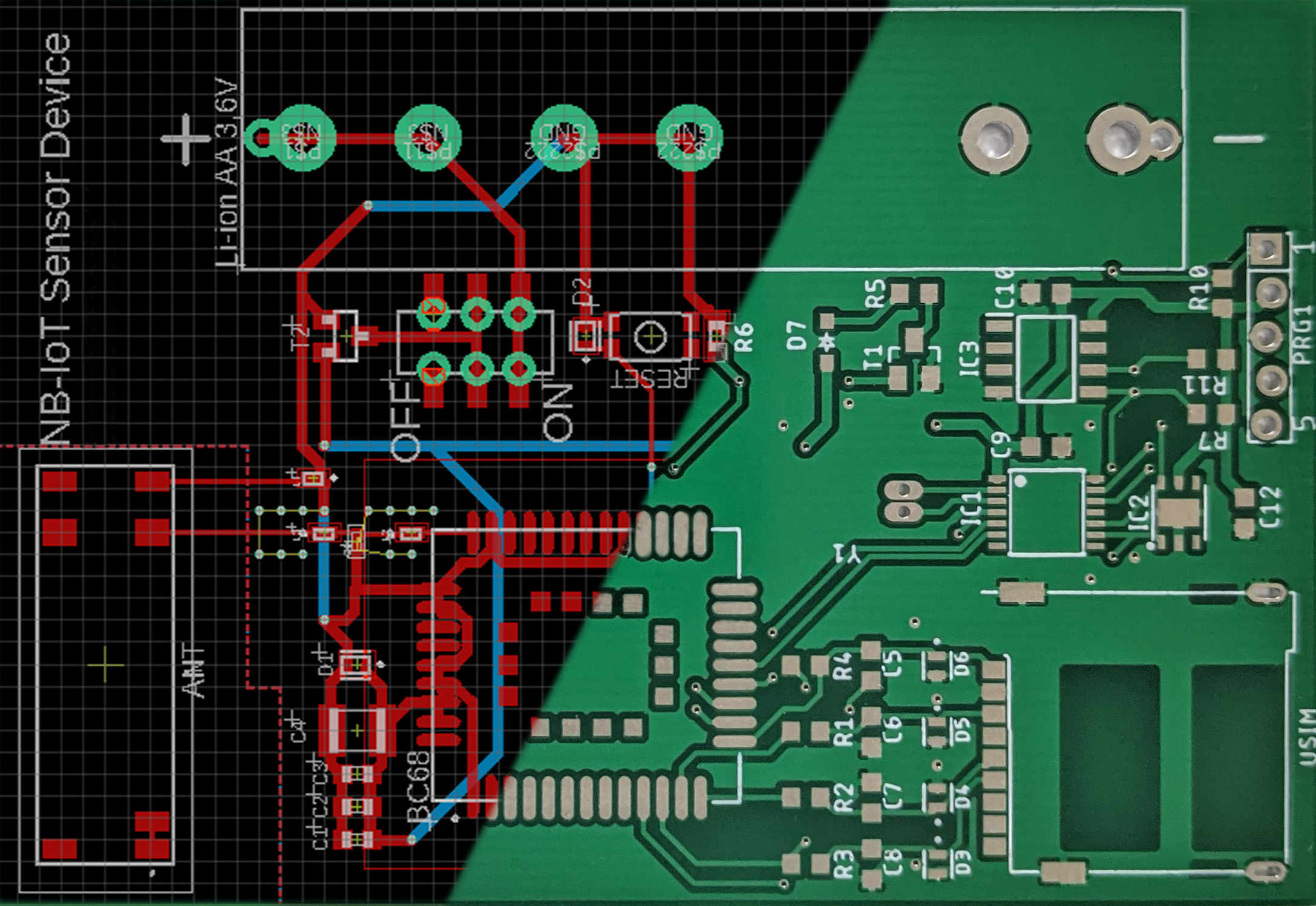
The Gerber format
Gerber is a vector format, which is used in PCB design. It is the industry standard. The format's function is to put each aspect of the PCB design (like copper layers, drill data, or solder mask) that is necessary for manufacturing the board, into separate files that are later used during the production to create the design.
Creating the Gerber files and including them in the order is the very first step in PCB manufacturing.
Gerber files uploaded to PCBnow are first thoroughly checked for imperfections and against the available design rules. They are then forwarded to begin the actual production of the design. If there is a problem with the design or with the files, customers are told, so they can check it.
1. Drilling the holes
After accepting the Gerber files the real first step in PCB production is drilling the holes.
There are three types of holes that can be drilled into a PCB:
- Vias: these holes have a very small diameter. They serve as a way to electrically connect the different layers of the PCB.
- Through holes: These are holes created for the THD components that are later soldered onto the board.
- Mechanical holes: These holes are made for screws or other components used to mount PCBs to different places.
The drilling is an automated process in which drilling machines automatically select the right size drill heads and drill holes to the correct places on the PCB based on coordinates and size data from the provided files. Thanks to the high-speed drills the walls of the holes are smooth and clean after the process. This provides a great basis for the metallization process of the holes in the next steps.
2. Copper deposition
In order for the holes to conduct electricity between the layers, they have to be coated with a conductive material. This is usually done by electrolysis. The problem is that after the drilling process the walls of the holes are not metalized, so electrolysis cannot be used.
This means that the first step of the metallization is to chemically deposit a very thin layer of copper on the inside of the holes. This copper layer ensures that in the next step the perfect amount of metal will be able to be deposited on the walls by electrolysis.
The deposition of the copper layer is a chemical process that involves the PCBs being dipped into different liquids. The dipping is done by machines, following the correct order of liquids. This guarantees the right thickness of the copper layer. The procedure is fairly fast thanks to modern machinery.
3. Imaging and photolithography
The photolithographic procedure is performed in a clean-room using high-end machines. The location ensures cleanliness so that no dust or other small particles can get on the surface of the PCB, which could cause problems within the circuit. The special feature of this area is that is lit with yellow light. The reason for this is that the PCB design drawings are printed on a material that is sensitive to UV (blue) light. This is called photoresist.
During the operation, the photoresist is placed on the sides of the PCB at hand. The film, which has the design outline printed on it, is placed on the corresponding sides of the panel. It is then exposed to UV light. The photoresist solidifies where it was not covered by the film. After that, the PCB is cleaned and the photoresist is washed off from the areas that were covered by the design pattern, leaving the resist on where it was not.
4. Plating
Surface plating is, in a sense, the continuation of the copper deposition. It is the next step in covering the drilled holes with a conductive material. During the process, the PCBs with photoresist are bathed into various liquids. The copper on the surface of the PCB acts as an anode during the electrolysis and thus the conductive metal layer is built on these copper surfaces.
The process is automated. The machines are programmed to leave the PCB panels in each bath for exactly as long as the thickness of the metal layer on the walls of the holes and the sides of the panel will be perfect. The metalized surfaces are thoroughly inspected, ensuring that the thickness of the applied conductive layer is perfect.
The final step of the plating process is to remove the unnecessary copper layer. This is the etching process. First, a layer of tin is applied to the board. This will protect the sensitive and necessary areas from the etching reagents. The rest, which is the photoresist, and the underlying copper layer are etched away from the board. The process is performed by machines and on a production line, which guarantees the fast and efficient execution of the procedure.
5. Automatic Optical Inspection (AOI)
Automatic Optical Inspection is performed by machines. The panels to be examined are manually inserted into these machines., making the inspection process very quick. During the inspection, the computers are constantly cross-checking the examined PCB with the corresponding Gerber files provided for the design. In case of a problem or error, the PCBs are remanufactured.
The speed and simplicity of inspection by machines significantly shorten the time of the PCB manufacturing process while at the same time they greatly contribute to the fast delivery of ordered designs.
6. Applying the solder mask
The outer sides of the PCB in production will be coated with solder paste. It is intended to provide protection for the conducting tracks as well as protection against possible errors that soldering could cause, like shorting the circuit.
The first step is cleaning and making sure that the surface of the PCB is free of dirt and dust. The panel is then sent into the yellow room, where the solder paste is applied by a machine on both sides of the boards at the same time. The mask is then dried in an oven. After that, the same photolithographic process is applied to soften the solder mask at the soldering pads of the design. Next, the mask is removed from the pads by washing. The solder mask that remains on the boards is further solidified by various methods.
During the procedure, the machines are under constant supervision. The cleanliness of the PCB and the quality of the solder mask is monitored and controlled, ensuring the high quality of the end product.
7. Applying silkscreen
The next step of PCB manufacturing is to put the symbols, text, and legend on the surface of the board. These are specified and customized by the designer engineer. The PCB is inserted in a machine and under a huge mesh. Under this mesh, there is a stencil of the inscriptions on which the machine presses the ink with the help of a squeegee. The ink will go through the stencil and print the required text on the surface of the board. later the ink is dried in an oven.
The other method is to simply print the labels on the PCB. In this case, the machines gather the necessary information from the digital plan. The printed ink is also dried in an oven. The whole process can be done in less than 10 minutes by inserting the PCB onto a conveyor belt, which takes it through a five-stage process.
8. Surface finish
Once the solder resist has been applied to the board, the panels must go through another surface treatment process. This procedure is necessary to keep the exposed copper surfaces (soldering pads) intact and protected until the soldering is done.
There are three possibilities to do it so:
- Hot air solder leveling (HASL): During this process, the panels are dipped into a tub filled with molten tin for a few seconds. After taking it out, the excess tin is removed by blowing very hot high-pressure air on the board. Following this, the tin layer on the soldering pads will be even.
- Hot air solder leveling without lead: This process is similar to the previous one. The difference between the two is that this coating is made with lead-free materials.
- Chemical gold plating: Gold plating is similar to the way copper is deposited at the beginning of the manufacture. There is no electricity involved, the process is purely chemical. It involves dipping the panels into different liquids to build the gold coating on the pads.
The surface treatment is also a highly automated process with pre-programmed machines, which's operation is watched-over to ensure the speed of manufacturing and the quality of the printed circuit boards.
9. Flying probe testing
10. Profiling and V-cutting
After the thorough testing of the circuit, the next stop is the cutting machines. Here the boards are cut from the production panel by machines, which use the digital design to do it so. The machines work with the dimensions specified in the design. They are able to automatically change drilling and cutting heads as required.
Alternatively, the panels can be v-cut. During this process, the machine does not cut out the designed PCB shape from the frame. Instead, it only makes the space between them thin, so that the PCBs on the panel can be easily snapped off from the panel. This technique is especially useful when it is easier to treat PCBs as a panel for the planting process and then easily tear the finished PCBs apart.